STANDARD 2N5109 AMP
This is a single 2N5109 broadband amplifier. It runs off 12vdc and draws 40ma current. It includes a 6db output attenuator that also provides a 50 ohm output.
This basic amplifier circuit is used everwhere a 10 to 20 db gain is needed. You see it often in homebrew construction. The circuit as shown here is the way I build it. The additional pictures show a recommended layout. I am publishing this particular version to document it for my future use.
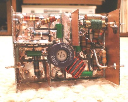
This is the finished amplifier without its three sided shielding cover. It also includes two end plates with feedthroughs for power, input and output. The input and output feedthroughs are made from #18 copper wire which is centered in a hole in the endplate. A scrap of teflon sleaving is installed over the copper wire to keep it from shorting to the end plate.
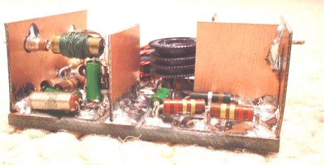
Another view of the finished amplifier. The completed unit is completely shielded. You may not need complete shielding in your application. Nearly all of my applications require shielding.
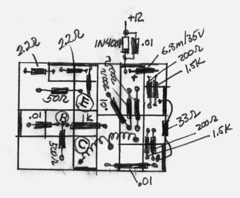
Note that there are several double parts that could be replaced by single parts if the proper value were available. The two 200 ohm resistors could be replaced by a single 100 ohm. The two 2.2 ohm inseries could be replaced by a single 4.4 ohm. The 200 ohm in parallel with the 1.5k could be replaced with a single 150 ohm. The schematic is drawn the way you see it because that is the way I build it. I have plenty of 1.5k, 200ohm, and 2.2ohm resistors but no 100 ohm, 150ohm, and 4.4ohm resistors.
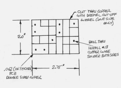
This is a sketch of the circuit board. The solid lines are grooves cut into the copper on one side of the double sided board. The grooves are made with a Dremel cut-off wheel and form isolated pads for the circuitry. Some of these pads are grounded by connection through holes to the grounded backplane on the opposite side of the board. Those pads that are not at ground are relieved at the edges to prevent unwanted shorts to the shields.
This is a sketch of the layout used with the circuit board.
-
HOME
OFF TOPIC BLOG
Amplifiers, audio
Amplifiers, RF
Antennas
Boatanchors
CW Keys
DRAKE radios
Equipment for Sale
Ham Radio Misc
Parts for Sale