This project began with my desire to find a very simple audio amplifier circuit. It needed to provide decent performance as well as simple circuitry. The 6EM7 amp may well be the ultimate in simplicity. Its performance is more than adequate.
The 6EM7 was used in TV applications as a vertical oscillator/amplifier. That particular application required very good linearity making the 6EM7 a very good candiate for class-a audio use. The tube contains two triodes in one evelope. One of the triodes is small signal with specifications similar to a 12AX7. The other triode is a power triode that has been compared to the 2A3 with indirectly heated cathode. The 6EM7 power triode is rated at 10 watts plate dissipation.
I used 6EM7s because I had them. 6EW7, 6EA7, and 6GF7s are all electrical equivalents to the 6EM7.
As long as there is at least 1v-pp of audio available, the 6EM7 can be used all by itself to provide a very linear two watts output into a speaker. In my case, I did not have 1v-pp audio available so I added a 6SN7 configured as a SRPP line amplifier which is capacitor coupled to the input of the 6EM7 amplifier section.
The simplicity of the direct coupled 6EM7 circuit suffers from some less than efficient power usage. This is caused by the 6EM7 tube specifications and is aggrevated by using direct coupling. The 6EM7 power triode is rated at a maximum plate voltage of 150 volts. The 6EM7 small signal triode is rated up to 300 volts on the plate. When using a B+ supply of 325 volts, a total of 3000 ohms cathode resistance needs to be used in the power triode circuit to prevent exceeding the maximum ratings of the tube. The 3k ohm cathode resistor splits the 325 volt B+, with about 150 vdc across the tube, the rest being dropped across the cathode resistor. The power triode runs at about 50ma plate current which also travels through the cathode resistor. Thus, the cathode resistor dissipates 7.5 watts which is equal to the power input to the tube. So the circuit is already running at 50 percent efficiency even before we take the 80 percent hit for running class-a. The overall result is that we have to input about 20 watts to get a 2 watt output.
Although the efficiency is low, the output is clean, and the total of 40 watts needed for a pair of monoblocks is well within the means of a fairly ordinary 325v/100ma supply.
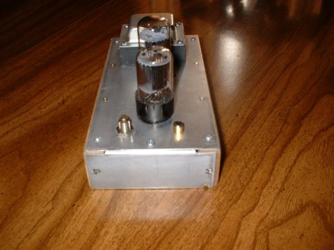
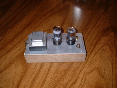
This particular amplifier project was built as two monoblocks with a seperate power supply built on a third chassis. Each monoblock chassis measures about 8 X 4 X 1-3/4 inches.
The power supply chassis measures 6 X 4 X 1-3/4 inches and includes a bottom plate that has 2-1/2 inch side panels extending below the main chassis. The power transformer, 5Y3 rectifier, and filter capacitor are mounted on the power supply chassis. The filter choke is mounted to one of the 2-1/2 inch side panels, external to the power supply chassis.
The sizes were chosen to be as small as practical to allow each monoblock to be located behind its respective speaker in a console. Such positioning permits speaker lead length of under two feet and power supply cable lengths of about three feet.
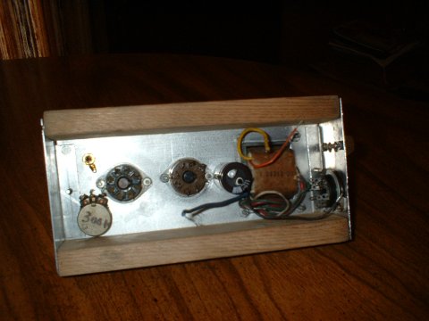
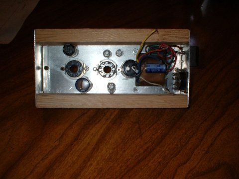
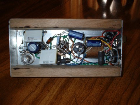
The monoblocks are identical. Layout and wiring is non-critical as long some basic good construction practices are followed. The filament wiring is twisted pair with all tube filaments wired in parallel. Chassis grounds are made only to a buss bar running the length of the amp and terminated at the input connector.
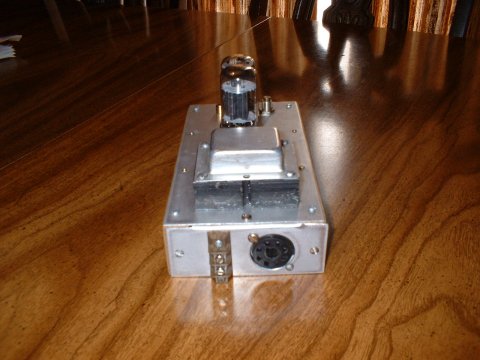
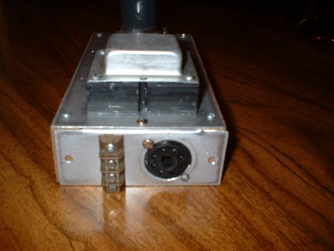
The power connection is made to an octal socket mounted at one end of the monoblock, in a side panel. The speaker terminals are mounted next to the power socket. Input is through a chassis mount RCA connector which is mounted to the top of the chassis close to pin 1 of the 6SN7. A 100k ohm pot is mounted across from the input connector. The pot is not really needed but might be desireable in balancing the output of the monoblocks.
Power cables were made from lengths of multiconductor cable. The cable plugs are slavaged bases from bad octal tubes. A nine conductor cable was used but only seven conductors were used as follows:
Pin 1 NC
Each monobolock chassis was constructed from 0.050 aluminum sheet. The top sheet was attached to two strips of cedar measuring 8 X 1/2 X 1-3/4. End plates were constructed from 0.050 aluminum sheet. Each end plate has a 90 degree bend, made by clamping the short end of the plate in a vise and bending using hand pressure. The short, 90 degree angles are attached to the top plate with one bolt. The bodies of the end plates are attached to the cedar rails with two wood screws.
The power supply was built on an old steel chassis of unknown origin. Size, here, was not as important but there was no need to make it any larger than necessary. The power supply is mounted at the center of the console permitting a maximum seperation between it and the monoblocks while allow the shortest possible length of power cable.
The decoupling capacitors are ordinary 10mfd/450v electrolytics. Cathode bypass capacitors are also electrolytics but they are paralleled with .68mf/400 volt mylars. Lower wattage resistors are all metal film. The high wattage resistors are ceramic wire wound units rated at 8 watts.
Since the monobolcks and power supply are located remotely, a remote power switch had to be used to turn the amp on and off. This is a toggle switch mounted into a small metal box and located at a convenient place on the front of the console.
I realize that monoblocks are not for everyone. An integrated, stereo version of this amp, with power supply can be built on a chassis plate measuring 8 X 12 inches. The actual size may vary depending on the size of the power and output transformers.
I have not used this amp with my turntable, but I am sure it will need an RIAA phono preamp. That might be the next project. A couple of 6SN7 sections with a passive RIAA network between them.
Pin 2 6.3vac ct grn
Pin 3 used as tie point for 1.5k power resistor and one leg of OPT.
Pin 4 B+ ground orange
Pin 5 325 v B+ blue
Pin 6 NC
Pin 7 6.3 vac white/grey
Pin 8 6.3 vac red/yellow
Pins 7 and 8 have two wires each.
-
HOME
OFF TOPIC BLOG
Amplifiers, audio
Amplifiers, RF
Antennas
Boatanchors
CW Keys
DRAKE radios
Equipment for Sale
Ham Radio Misc
Parts for Sale