A digital dial has the advantage of allowing us to read the frequency directly off a display instead of having to interpolate the hash marks on a mechanical dial. The crystal calibrator will still be needed to provide a signal source for peaking the receiver, but it is now no longer required for setting the mechanical dial for accuracy.
Ideally, we would want the digital dial to readout the exact frequency of the signal we are receiving. That is what happens with radios using PLL technology. The R4A does not use PLL technology. The result is that EXACT frequency readout is not possible in all modes.
We can get EXACT frequency readout in only one mode. If we tweak the frequency to be accurate in CW, it will be off in USB and LSB by as much as the offset of the sideband to the carrier.
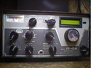
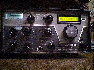
FINAL PRODUCT WITH REDUCED BACKLIGHTING INTENSITY
Digital dials are simply frequency counters. They work by sampling a frequency and displaying the result. If we shift from USB to LSB using passband tuning, there is no change in any signals generated in the receiver. So there cannot be any change in what the frequency counter sees. You will have the same frequency displayed in USB as in LSB.
Other than that, the digital display is a handy feature.
There are two ways to implement a digital display using the Almost All Digital Electronics (AADE) digital dial kits. The AADE kits are easy to assemble and easy to use. They are reasonably priced at about $50 a kit and are small enough to comfortably fit into the R4A.http://www.aade.com/
Power requirements are 9VDC at about 10ma for the display. If a backlit display is used an additional 200 to 300 ma of current will need to be supplied. That additional current can come from the same 9 vdc supply. Or all the power to run both can be obtained from a 12 vdc, 1 amp supply. DO NOT attempt to power the dial by dropping voltage from the 150 vdc bus, like Drake does with the PTO. More on this later.
One way to add a digital dial is to use the AADE DFD1 kit. The DFD1 is a simple frequency counter with display. It accepts a single frequency input and displays the result. To use it, we connect its frequency input to the INJ signal in the R4A. Now the INJ signal will be 5645KHZ higher than the actual frequency of the signal being recieved, but this will be true for all bands and frequencies. The DFD1 has three trimmers and a configuration jumper to provide a plus or minus frequency offset. The trimmers are set to show 5645 on the display with the input to the counter grounded. Then the offset jumper is set for a minus off-set, and we get an actual frequency readout.
The only problem with the DFD1 solution is that the INJ signal is only strong enough to drive the display when the preselector is peaked properly for the band being used. Under all other conditions, the display will show 5645.
That is not a particularly difficult quirk to get used to, but it is radically different from what we have been conditioned to accept from other radios with digital dial readout. Actually, the quirk does have a positive aspect in that if 5645 is displayed, you know that either the preselector is not peaked, the aux crystal switch is not in the correct position, or the xtal/vfo switch has inadvertently been pushed back to the xtal position.
The other way to add a digital dial is to use the AADE DFD2 kit. The DFD2 does not cost anymore, but it does have some additional freatures. Although it too is a simple frequency counter, it will accept three independent frequency inputs and calculate the result before presenting it on the display.
This allows us to feed the Hetrodyne Oscillator, PTO, and BFO signals to the display and calculate the result which should be the frequency being received. This may be a better solution because these three frequencies are present at respectable levels all the time. However, there may be some pre-selector interaction with the Hetrodyne Oscillator signal. This signal is peaked by the pre-selector. So you may end up with the same problem as before except in this case the display will not show 5645 but some other set of digits. I have not used the DFD2 so I cannot say for certain if this is a real or imagined problem.
The degree of frequency inaccuracy is still the same with both the DFD1 and DFD2. Note that this is not a deficiency of either of the DFD's. It is caused by the way the signals are processed in the R4A. You would experience the same problem with any other frequency counter based digital display.
The only way around this is to use a PLL to synthesize the frequency. Such a conversion is not recommended. For one thing it would require some major work. For another, it would introduce phase noise. I am assuming that the reason we are using a radio such as the R4A is to get away from phase noise. If that is not a factor, sell the R4A and get a radio using a PLL with factory frequency display built-in.
Now for more on the power supply.
Both DFD's require the same type of power. A backlit display is highly recommended even though it adds another 10 dollars to the cost. The total power requirement will be 9 volts at up to 300 ma. Actually, anything between 9 vdc and 15 vdc can be used as long as the current requirement is met.
The 13 tube R4A has sufficient room under the chassis, behind the volume control pot, to add a small 12 vac transformer. The 11 tube R4A does not have much room to spare. In the case of the 11 tube radio, Additional space can be obtained by replacing the 6EH5 audio output with a solid state audio output. However, this can lead to more complications and more work.
DISPLAY ON BRACKET - SIDE VIEW
A bridge rectifier and filter capacitor will get us about 17 volts DC out. That is a little high for our application. We could drop the voltage using a series resistance but then volage regulation will be at the mercy of this resistor and any variation in load. We might want to adjust the current to the backlight to get the right amount of illumination. Perhaps even install a potentiometer to vary the brightness under varying ambient light conditions. Such a variable load may cause us problems unless we use a three terminal regulator.
The three terminal regulator is better because it provides additional filtering as well as regulation and short circuit current limiting. By adding a capacitor to ground from the ADJ pin of the regulator we can reduce the ripple content to an unmeasurable level.
Note that in order to do this we need access to the regulator's ADJ pin. Fixed voltage regulators do not have an ADJ pin. This procedure is designed for use with LM317's.
This trick to reduce ripple may also allow us another power supply alternative. We cannot just throw a bridge across the 12 volt filament supply because one leg of the filament supply is connected to ground. However, we can connect to the hot side of the filament supply and install a diode rectifier creating a half wave supply. Normally, half wave supplies have poor regulation and bad ripple. However, when used with an LM317, and ADJ pin filtering, the regulation should be good and the ripple reduced to an acceptable level. This alternative has not been tested, but appears to be a viable alternative to adding a seperate power transformer.
Once we have a ripple free, well regulated source of DC power, it would make sense to use it for the PTO and perhaps other low voltage needs in the original R4A. There are several cautions to observe before we do this.
The most important caution is to make sure we have a current limiting resistor in series with each load. This is particularly important for the PTO supply. The PTO has a 10 volt zener diode connected between the B+ input and ground. This diode is internal to the PTO. It is easier to just add a 100 ohm series resistor than remove the diode, but removal is an option since it would no longer be needed if we provide well regulated voltage to the PTO.
Don't remove the OB2 if this is a 13 tube R4A. The OB2 is used to provide regulated voltage to the tube-style crystal calibrator.
Finally, we get to mechanical considerations.
To make this fit, the PTO needs to be stripped of all mechanical parts. These include the gear mechanism, dial, locking rings, washers, and main tuning knob skirt. The dial window will also need to be removed and the dial window opening in the front panel needs to be enlarged. The window needs to be about 1/8th inch wider to allow the bezel to fit. Carefully file off 1/16th inch on either side. Do a neat job in case you want to restore the mechanical dial at a later date. Save all the parts. Maybe put them in a plastic container and keep them inside the converted radio where they will not get lost.
The PTO will need to be completely removed to make these modifications. It will also need to be remounted about 1/4 inch further back from its original location. Otherwise there will not be enough room for the display and bracket. The PTO shaft is long enough to allow it to be relocated but there will not be enough room for both the knob and skirt. The skirt is not needed for use with the digital display.
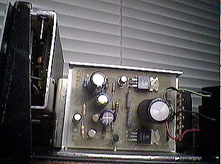
The photos show the basic mechanics of the mounting. The display is bolted to an aluminum bracket using 2-56 hardware. Exact location is important for a perfect alignment with the front panel. The bracket can be made from a larger piece of aluminum angle or it can be pieced together with smaller angle and flat sheet. The idea here is to completely cover the counter and display to provide electrical shielding and reduce the possibility of introducing unwanted noise into the system. Use ferrite beads, shielded cable, and by pass capacitors on all leads except the INJ input to the counter. Use shielded cable for the INJ lead too, but leave the bypass cap and bead off. Cable made of teflon insulation is highly recommended. It will not melt under the heat of the soldering and will not short center lead to ground.
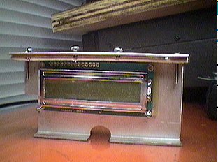
DISPLAY MOUNTED TO BRACKET
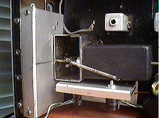
The bracket is mounted into the radio with four self tapping screws. Four holes are drilled into the top of the vertical portion of the chassis. These holes are space along the area covered by the bracket. These holes are clearance holes for the self tapping screws. The self tapping screws, tap into the aluminum bracket to keep the bracket in place. The bottom of the display bracket will need to be cut out to allow clearance for the PTO shaft and drive gear. Do no attempt to remove the small drive gear from the PTO shaft.
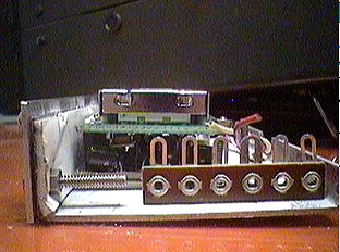
DISPLAY AND BRACKET INSTALLED - TOP VIEW
FRONT VIEW WITH INTENSE BACKLIGHT
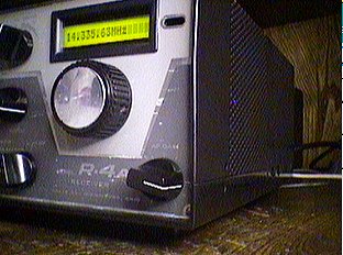
SIDE VIEW WITH INTENSE BACKLIGHT
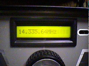
CLOSEUP WITH INTENSE BACKLIGHT
DISPLAY AND BRACKET INSTALLED - SIDE VIEW
I hope you like green or yellow as a backlight. Blue, and also white displays are available but they are dual line instead of the single line we need. They are also very expensive, costing more than the DFD kits. Vacuum flourescent displays may also be used but the interface to the counter will need to be changed, not a simple task. For now, green or yellow, seem to be only decorator colors available. Green is obtained by running about 100 ma. to the backlight. Yellow shows up when 300 ma. is provided. It is better to run the backlight at the lower current. Less heat and more life.
-
HOME
OFF TOPIC BLOG
Amplifiers, audio
Amplifiers, RF
Antennas
Boatanchors
CW Keys
DRAKE radios
Equipment for Sale
Ham Radio Misc
Parts for Sale