This modification has not been very popular in the past because it brings no significant advantage as long as domestic 6JB6's are available and affordable. That is no longer the case. The 6JB6 is becoming harder to find and commands a $25+ price tag each. Matched pairs are even harder to find and more expensive. What started as an excellent economical solution has ended up being a collectors nightmare.
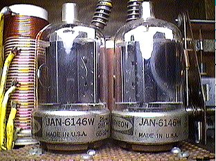
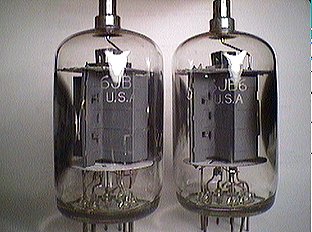
6146/6JB6 COMPARISON
As long as we are talking tubes, here is a comparison of the 6146 and the 6JB6.
TUBE DISS PVOLTS SCRVOLTS SCRDIS FIL V/A CIN COUT CGP
6146 35W 750 200 3W 6.3/1.125 13P 8.5P .22P
6JB6 17.5W 500 200 3.5W 6.3/1.2 15P 6P .2P
For use in AB1 operation the 6JB6 is rated for 35 watts
output.
For use in AB1 operation the 6146 is rated for 61 watts output.
Now we all know that Drake pushes the 6JB6 a little harder than what is shown above. A good set of 6JB6's should deliver about 120 watts output on 80 and 40 meters with about 100 watts on 20, 90 watts on 15 and 75 watts on 10.
Note that 6146's do not need to be pushed to get comperable performance. Note the close match on the inter-electrode capacitances. My book of tube specs rate the 6146 to 60mhz while the 6JB6 is only rated to 30mhz. Note also that the 6146 has a maximum plate dissipation almost twice that of the 6JB6. A pair of 6146's running class AB2 with a plate voltage of 750 volts will deliver an output of 131 watts. Using the 6146, we can expect to get a little better power output up to 10 meters. Ten or twenty extra watts are not going to make much difference when added to 75 watts, but there is no reason to push the 6146's to that level. Notice that with twice the plate dissipation, the 6146's are less likely to complain and will probably outlast a pair of 6JB6's that are being pushed for power output.
To summarize, 6146's are a better choice because:
1. They will probably be available longer.
2. There is current new production in China.
3. Their ratings imply they will last longer.
4. They are true transmitting tubes.
5. They promise slightly better performance on the higher frequencies.
6. You can expect slightly better linearity at higher power levels.
7. Collins uses them, why shouldn't Drake owners use them too?
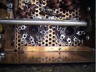
WITH COVER INSTALLED
I have heard horror stories about the mechanical aspects of the conversion. True, 6146's are a little larger than 6JB6's. Standard 8-pin tube sockets will not fit the holes used by the Novar sockets. Biasing and AGC has to be modified. For top performance the 6146's need a higher plate voltage.
While there is some truth to these stories, most of them are exaggerated. When done correctly, the conversion does not require any sheet metal work.
There are 8-pin tube sockets that will fit the Novar socket holes. In fact, the same hardware that was used to hold the Novar sockets can also be used to mount the new 8-pin sockets. The 6146's are not too tall for the enclosure and do not need to be dropped below chassis level. To accomplish this you will not be able to use those neat ceramic plate caps on the 6146's, but there is adequate room for smaller, spring style plate caps that are lower profile.
TOP VIEW
NEW SOCKETS - TOP VIEW
If you are still with me, lets take the modification one step at a time.
FIRST, make sure you have a working transmitter. Trying to trouble shoot a broken rig after it has been modified will be more difficult. Make sure that it is functioning to specifications before attempting any modifications.
SECOND, take notes. Make sure you understand the functions of the five feedthrough connections to the final bay. Hint: the one closest to the rear panel is the plate supply. The next one up is the cathode return. The next one up is the screen supply. The next one up is the bias. The last one is the filament supply.
THIRD, compare the conversion schematic to the unmodified schematic. Note the standard, physical 6JB6 connections. Write them down should you later need to go back to using 6JB6's. Take note of the lead dress.
FOURTH, unsolder all connections to the existing tube sockets so they can be removed. The ground rings of these sockets are soldered to the chassis. Unsolder them. Don't just pry them loose, it might damage the old sockets and the chassis. Save the old sockets and all parts removed. Primarily the old cathode and screen resistors. It is also best to just leave the bypass capacitors installed on the old sockets and use new capacitors for the 6146's.
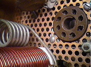
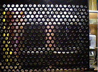
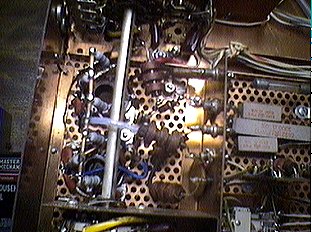
10 METER COIL SPACING
At this stage we have removed quite a few parts. The final amplifier circuitry is easily accessible and should be checked for cleanliness. Inspect it for dust bunnies, dirt, and accumulated grease. If it looks like it could use cleaning, now is the time to do that.
I use a solvent like 409, but I use it sparingly and localize the application. Let the solvent work for a few minutes before rinsing. Rinsing is best done over a kitchen sink with hot water from the spray attachment. Be careful. We do not want to dunk the transmitter in water. We just want to remove the solvent and dirt. Afterward, allow the transmitter to dry thoroughly. You can speed up the process by using a hair dryer but I would still recommend leaving it to dry overnight before applying power. Make sure there is no residue or moisture before applying power.
If the parts under the final amplfier cover are really gunked up, it is best to remove them and clean them individually. Take care not to soak the antenna relay coil. In case it does get soaked, bake it in an oven or let it dry for a week before trying to use it.
Note that this antenna relay coil is not of the garden variety type with 12 vdc coil rating. This is what is known as a 'plate coil'. It is a high impedance coil, run off 250 vdc, and activated by one half of the 6EV7.
New, replacement relays are no longer available. It may be a good idea to remove this relay before doing any serious cleaning. Then, as long as it is out, inspect the contacts. If they are not bright and shiny, burnish them by running some paper across the contacts using mild pressure. Do NOT use a file, sandpaper, or common burnishing tool on these contacts.
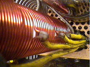
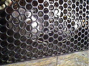
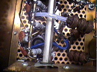
10 METER COIL SPACING - CLOSEUP
FIFTH, before installing the new 8-pin sockets, wire them. It is very difficult to wire the connections with the sockets installed.
The two sockets will be wired identically except for the filament connection. Pin 2 of one of the sockets will need to be wired to the socket ground ring.
Start by connecting a bus wire between pins 4 and 6 of each socket.
Install .005/1kv ceramic bypass capacitors from pins 3, 4, 6, and 1 to the ground ring. Install 470pfd capacitors from pins 2 and 7 to ground. Use the shortest leads possible and make good soldered connections. The socket that has pin 2 grounded does not need a 470pfd bypass.
Install 10 ohm/1 watt resistors on pins 1, 6, and 4. Wire wound resistors will work here but metal film are smaller and will be a better fit. Use short leads and good solder connections. Allow the resistors to extend vertically from the sockets. All six resistors will be connected to a bus wire for connection to the cathode RF choke. The wire resistor leads are sufficient to support the #12 bare bus wire.
Install three inch lengths of hookup wire to pin 3 for later connection to the screen grid power source.
Connect pins 8 of each socket to ground. This pin is connected to the base rings of the tubes.
After the sockets are wired and still loose, clean the flux off the soldered connections. Inspect the work. Then install the sockets into the transmitter. The index pins on the sockets should point to the tank coil and plate choke on top of the chassis. Use the captured nuts and screws that were used to hold the Novar sockets. The socket with the grounded pin-2 should be installed closest to the back of the radio.
NEW SOCKETS - SIDE VIEW
Solder the tube socket ground rings to the copper chassis in at least two places per socket. This will require at least a 50 watt iron. You can also use two 25 watt irons, used together to increase the amount of heat. Polishing the copper under the areas to be soldered will be a big help. Most people use too much solder in an attempt to liberate more flux. Should you get any solder drips, find them and remove them before applying power. Good soldered connections are very important here to allow the bypass capacitors to do their job.
Wire pins 5 together using the same brass strip from the old installation. This strip is supported by the #5 pins and the connection to the 500pf capacitor and bias RF choke. Similar to the original installation.
Connect the screen supply hook-up wires directly to the screen supply RF choke at its terminal strip. Dress these leads down toward the chassis and keep them as short as possible.
Use a short length of bus wire to connect pin 7 of the backmost tube to pin 2 of the frontmost tube. Bend and dress the wire so it does not short to anything.
Reconnect the filament supply to pin 7 of the frontmost tube.
Reconnect the 500pf capacitor and the bias RF choke to the end of the brass strip. Be sure to do this after wiring the filament choke as the bias RF choke will cover up the filament connection to pin 7 of the tube socket below it.
Wire the loose ends of the six 10 ohm resistors to a three inch length of #12 bare bus wire. Space the connections evenly on the wire. Use some smaller bus wire (a resistor lead scrap) to extend the cathode RF choke connection. Install a bit of sleeving over this connection and terminate it to the middle of the cathode bus wire. This lead will have to be routed across the band switch shaft. Dress the lead afterward so that the band switch shaft does not rub against the lead.
Solder a short length of wire across the 1.5k ohm resistor which is in series with the bias supply.
Connect a 100 ohm, 1 watt, resistor in series with the screen power lead going to the feed-through bulkhead. Add a teflon stand-off to hold the other end of this resistor and the original screen supply lead.
Connect a 15k ohm, half watt resistor from the plate of V1B (AGC amp) to ground. This may only be needed on the T4X to correct a factory screw-up. The original value of the resistor here was 1 meg which would ensure that there was no AGC action. No one really noticed so it may not be a big deal. If you want the AGC to work on an old T4X, install the 15k resistor. No need to remove the original 1 meg resistor, just wire the 15k arcoss it.
Look at the neutralizing capacitor. If there is a fixed capacitor installed across it, remove that capacitor.
Check all connections. Inspect lead dress for shorts.
NEW SOCKETS - BOTTOM VIEW
SIXTH, Temporarily connect a 50 ohm 1 watt, non-inductive resistor from the grid connection to ground to act as a load for the 12BY7. Now, with the 6146's still out of the sockets, connect the power and turn on the transmitter. Check it out thorougly. Make sure it is still working properly. Monitor the low level signal from the 12BY7 on a receiver and make sure it works in all modes. Check the voltages on the 6146 socket pins. The plate voltage should be no higher than 800 volts (in case you are using a supply other than the standard Drake supply). Screen grid voltage at pins 3 should be 250 volts. Filament voltage at pin 7 of the socket closest to the front panel should be 12vac. Bias voltage at pins 5 should be adjusted to -90 volts with the function switch in CW mode.
You might need to modify the bias voltage divider circuit to get the -90 volts. This circuit is inside the power supply. The wiper of the bias adjust pot is grounded. One of the remaining terminals on the pot has a 6.8k resistor attached to it. Solder another 6.8k resistor across it. A resistor from 5k to 10k will probably work. The adjustment range is not critical. It just needs to be able to get to -90 volts.
When everything has been checked, turn off the power and install the 6146's. Don't forget to remove the temporary 50 ohm resistor. Connect the plate caps. Inspect the solder connections at the plate caps and RF choke. Look for cracks and loose connections. Better yet, just resolder the connections. Install the high voltage cage. Connect the RF output of the transmitter to a dummy load rated for at least 100 watts.
Whatever you do, don't run the finals without plate voltage. Doing so will make the screens act as plates which could damage the tubes.
Select the 80 meter band. Turn on the power. Let the new finals warm up. Check to see that their filaments are lit. Switch to the tune position and note the plate current meter reading after obtaining a dip. It should be below 100 ma. Tune up the transmitter normally but don't load it for more than 75 watts output or about 125ma plate current. Monitor the signal and see if it sounds okay.
If everything is working fine, neutralize the finals using the normal procedure in the Drake manual.
Once neutralized, repeak all the trimers for maximum RF drive on all bands.
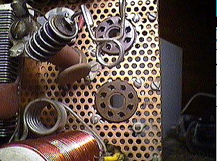
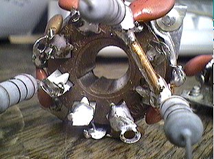
OLD SOCKETS
Use the transmitter in the same way it was used with the 6JB6's. Don't exceed 320ma total plate current in CW mode. Don't exceed 250ma total plate current on peaks in SSB mode.
At 750 volts and 320ma we have an input power of 240 watts in CW mode. You can expect a solid output of 160 watts in this mode.
AT 750 volts and 250ma we have an input power of 187 watts in SSB mode. You can expect a solid output of 112 watts on peaks in SSB mode.
At 650 plate voltage these values will be reduced, but you should still get performance on par with the original 6JB6's.
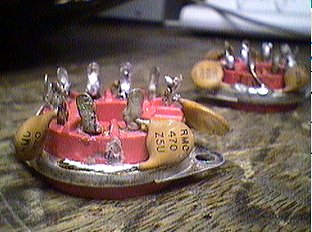
NEW SOCKET WITH NEW PARTS
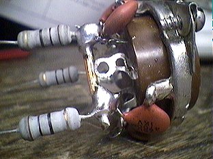
NEW SOCKET WITH NEW PARTS - CLOSEUP
NEW INSTALLATION
NEW INSTALLATION - CLOSEUP
Tetrodes and pentodes, when run in grounded cathode operation, like here, require good screen voltage regulation for maximum linearity.
The 250 volt supply in the standard Drake supply is fairly 'stiff' with plenty of current. Even so, check the screen grid voltage at low and high power output to make sure it stays at 250 volts. A plus or minus 5 volt variation is probably okay. Anything more, and you can improve the linearity by adding screen grid regulation.
Adding regulation is simple. We can use high voltage 10 watt zeners. There is plenty of room under the chassis to locate a couple of zeners mounted to a thick strip of aluminum to act as heat sink. The 2500 ohm power resistor in series with the screen supply can be used 'as-is' to supply current limiting to the zener regulator connection. The zeners would be connected from the screens of the tubes to ground with proper polarity observed. A .005mfd/1KV capacitor across the zeners will take care of zener noise.
The open air configuration of the cabinet and high voltage cage allows for convection cooling of the finals. This works, but the cooling can be improved significantly by adding a small fan to the back of the high voltage cage. We do not need a high volume fan here because forced air cooling is not required. All we want is air circulation a little better than what can be expected by convection alone.
A 12vdc, three inch fan, commonly found in computer power supplies is perfect for this application. It fits perfectly onto the back of the high voltage cage, but requires four holes drilled into the cage for mounting. A smaller fan can also be used without the need for additional holes. The smaller fan can be mounted through existing holes in the cage.
Power for the fan can be obtained from the 12vac filament supply. A simple half wave rectifier and 100mfd filter capacitor will generate about 20 vdc for the fan. The voltage can be dropped to under 12vdc at the fan by using a one watt resistor. The value of this series resistor will depend on the current required by the fan and on how much air you want to move. Values between 50 and 300 ohms seem to work fine. If you use a resistor that is too high in value, the fan may not even turn. Also, the fan motor requires the plus voltage applied to its plus lead which is normally red. A reverse connection here will not damage the fan, but it will not work.
At 11 vdc, these fans become whisper quiet and still move lots of air. There is plenty of room under the chassis for the extra components. A couple of stand-off terminal can be installed through the main chassis ventilation holes to provide an extra terminations for the additional parts.
-
HOME
OFF TOPIC BLOG
Amplifiers, audio
Amplifiers, RF
Antennas
Boatanchors
CW Keys
DRAKE radios
Equipment for Sale
Ham Radio Misc
Parts for Sale