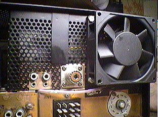
REAR VIEW OF FAN INSTALLED
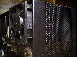
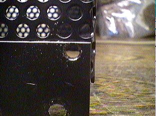
SIDE VIEW OF FAN INSTALLED
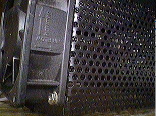
CLOSEUP OF THE THE FAN INSTALLED
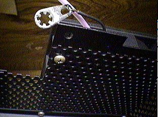
SCREW HEAD AT THE INSIDE OF THE RF COVER
If a three inch fan is used, the RF cover will need to be dr illed for the installation.
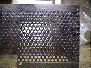
LOCATION OF THE FOUR HOLES IN THE COVER
The cover is steel. It will rust if the new holes are left unpainted.
CLOSEUP OF HOLE AFTER PAINTING
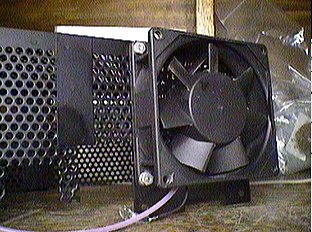
A 3 INCH FAN INSTALLED TO THE RF COVER
Power for the fan is obtained from the 12 vac filament supply. A single diode, half wave rectifier is used. It is filtered by a 100mfd/35vdc capacitor. A 51 ohm 2 watt resistor is used to reduce the voltage to the fan to about 11 vdc. The result is a whisper quiet fan and plenty of air movement. The actual value of the series resistor will vary from 10 ohms to 100 ohms depending on the current needs of the fan and your desire for airflow. Most fans of this type need current around 150ma. and voltage from 8 to 12 volts dc.
TOP VIEW OF CHASSIS SHOWING STAND-OFF LOCATIONS
Two teflon insulated stand-offs are used to support the additional components.
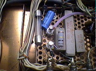
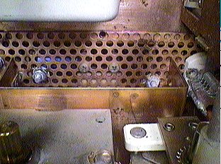
UNDERSIDE OF CHASSIS SHOWING ADDED COMPONENTS
There is plenty of room for the diode, resistor, and capacitor. The diode is connected from the filament supply to the final cage to one of the stand-offs. Cathode to the stand-off. The same stand-off is connected to the plus side of the capacitor. The grounded end of the capacitor is soldered to an existing ground lug in the radio. The resistor is mounted between the two stand-offs. Power for the fan is taken from the second stand-off. Teflon sleaving is used to protect the power lead. The return side of the fan motor is connected to a solder lug which is installed under one of the screws holding the RF enclosure.
The additional cooling should significantly improve tube life.
I AM OFFERING A KIT TO ADD A COOLING FAN
Included are:
1 - 12 vdc ball bearing fan (2.5 inch)with mounting hardware.
1 - 100mfd/35vdc capacitor
1 - Silicon Rectifier Diode
1 - 51 ohm 2 watt resistor
2 - Teflon insulated stand-offs and mounting screws
1 - Solder lug
1 - Complete instructions with schematic.
THE KITS ARE SOLD OUT AND NO LONGER AVAILABLE
The advantages of buying a kit are convenience and support.
All parts to do the conversion are included in the kit. With the exception of tools and solder, there is no need to scrounge for parts.
All kit purchases are guaranteed to result in a working modification. I will provide whatever support is needed to get your modification up and running.
-
HOME
OFF TOPIC BLOG
Amplifiers, audio
Amplifiers, RF
Antennas
Boatanchors
CW Keys
DRAKE radios
Equipment for Sale
Ham Radio Misc
Parts for Sale